Overview

The purpose of this project is to create a quadcopter from the ground up using the techniques which were taught in Introduction to Embedded Systems. This includes writing software, designing hardware, and PCB design.

The CodQuaptor has the ability to maintain steady flight at a prescribed altitude and will constantly adjust its attitude to make up for any chagnes in it's surroindings. This is all done through error correction at the hands of the CodQuaptor's 3 PID Controllers. Data is sent to the quadcopter through an accelerometer and proximity sensor. The motors are controlled by PWM and the accelerometer and height information are relayed to the microcontroller through I2C Channels. Additionally, there is battery protection software in which the microcontroller will poll the status of the battery and will alter the performance of the system based on the available voltage.

Software

The software is where most of the work for this project went. It inludes all of the functions necessary for operation with additional saftey features. This is mainly the ability to take in data from the sensor and alter it until it is a useable PWM signal for each of the motors.

Features

  • PID Controllers
  • Motor Control Algorithm
  • Battery Health Checks
  • Status LED Control
  • Error Handling
  • Serial Communication

PID Controllers

The main part of the controlling algorithm in CodQuaptor are the three implemented PID Controllers. The three controllers represent the height, roll, and pitch of the device. When the error is determined from these controllers the value is normalized for use with the motors.

Motor Control Algorithm

In order for the PID controller data to be used to control the motors, they were sent through an algorithm which generated the correct PWM signal for each motor. In order to generate the final result, the roll and pitch value was divided in half and then added or subtracted to the height value, depending on the position of the motor. In order to prevent any kind of positive feedback loops in the motor control the roll and pitch number was added to one side, and then subtracted from the other. This will balance the device and prevent the motors from maxing themselves out.

Battery Health Checks

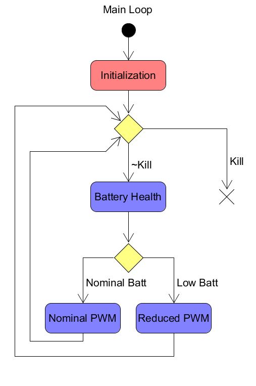
To prevent damage to the device and the on-board battery, there are constant battery checks occuring inside of the main function. This uses a wire attached from the MSP430FR5994's ADC to the battery to determine it's current voltage. There are three states of battery health: Optimal, Low, and Critical. When the device is in an optimal battery state, it functions normally. When the low battery state is entered, the device will decrease the power sent to the motors which will hopefully lead to a successfull landing. As soon as the device enters a critical battery state, the motors and LEDs are all disables, and the MSP430 enters a low power mode until the device is reset.

  • Optimal   > 3.0 V
  • Low   2.9 V - 2.7 V
  • Critical  < 2.7 V

Error Handeling

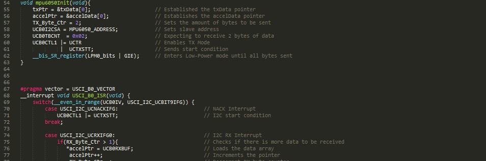
To prevent any I2C errors from crippling the function of the device, whenever a NACK is received from the slave device, the master will resend a start condition to reestablish the I2C Communication.

Status LED Control

In order to indicate the status of the battery to the user, there is an LED placed on each of the arms of Codquaptor which display the battery health. In an optimal voltage state, the lights remain in a constant on state. When a low-power state is entered, the lights will begin to flash with a 50% duty cycle. Once the critical battery plane is entered the lights will shut off along with the motors.

Serial Communications

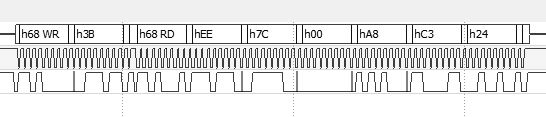
I2C and UART are both implemented into the software to allow for simple communication with all of the ICs on board. I2C is used between the MSP430, the proximity sensor, and the accelerometer. UART is used to talk to the MSP430 chip from a computer. Below is an example data read from the accelerometer showing how the data will be displayed to the processor. First, the master enters write mode and sends the address it wants to read from. The next 6 received bytes are the X, Y, Z values with the most significant byte sent first.


Operation Block Diagram

Hardware

The hardware for this design needed to account for all of the necessary components for a quadcopter. Things like noise reduction and ground plane separation went into account when designing the circuit board. The board was designed in such a way where the motors can mount directly to the PCB, which eliminates the need for an external frame.

Features

  • Low-Side Cwtich PWM-based Motor Control.
  • Voltage regulation.
  • Easy-Access I2C Viewing Header.
  • UART Connection.
  • Detachable Voltage Regulator.
  • Programming Header.
  • Motor Mounting Holes.

Low-Side Switch PWM-based motor control

In order to control the propeller speed, PWM was used to control the motors. This required the used of a MOSFET switch to supply the motors with an adequate amount of current. One design choice which needed to be made here was whether to use a high-side switching architecture or low-side. High-side switching was the final decision, to avoid running extraneous traces through the legs of the PCB board.

Voltage Regulation

The final design is powered off of a 3.7 V LiPo battery. The optimal voltage for most of the IC components used in this design run optimally on 3.3 V, so voltage regulation needed to be implemented. Additionally, voltage regulation protects the circit from any spikes in voltage which may in turn damage the components.

Easy-Access I2C Viewing Header

For prototyping purposes, there are headers connected directly to the I2C lines of the board, which allow an outside user to tap into the line to see just what is being sent. This was done to ensure that the devices are talking to each other correctly and to provide as a good platform for debugging incase something goes wrong.

UART Connection

In order to tune the PID controllers of CodQuaptor, there are exposed UART channels on the board which provide a simple means of tuning the device. In order to control the PID Controller, 9 bytes of data are sent to the board which determine the constants for each of the controllers. The microcontroller will respond with an acknowledge byte when all of the data is recieved.

Detachable Voltage Regulator

Incase there is an issue with the voltage regulator, or the device needs to be powered from a separate source other than the battery, there are pins available which bypass the voltage regulating circuitry. This will allow for reliable debugging without having to rely on the battery to supply adequate voltage.

Programmable Header

In order to program the microcontroller, there needs to be a spy-bi wire interface on the PCB board. This is done in the form of a header which have traces for a 3.3V line, Ground, Test, and Reset. This allows for the chip to be programmed straight from the launchpad chip.

Motor Mounting Holes

To remove the need for an external frame around CodQuaptor, the PCB board was designed with holes availble to mount the motors. In order to reduce any kind of yaw applied to the device while it is in operation, the motors are installed in a specific fashion to reduce any angular force. This is done by altering the direction of each motor. The pitch of the props need to be changed aswell, but over this is a simple solution to removing any kind of yaw force.


PCB Schematic

Technical Info

Helpful Links


Pin Assignments

Number Name Purpose
1 P1.0 GPIO (LED)
2 P1.1 GPIO (ADC)
10 P1.4 TB0.1
11 P1.5 TB0.2
22 TEST TEST
23 RESET RESET
24 P2.0 UCA0TXD
25 P2.1 UCA0RXD
27 P3.4 TB0.4
28 P3.5 TB0.3
31 P1.6 UCB0SDA
32 P1.7 UCB0SCL

Elements

Text

This is bold and this is strong. This is italic and this is emphasized. This is superscript text and this is subscript text. This is underlined and this is code: for (;;) { ... }. Finally, this is a link.


Heading Level 2

Heading Level 3

Heading Level 4

Heading Level 5
Heading Level 6

Blockquote

Fringilla nisl. Donec accumsan interdum nisi, quis tincidunt felis sagittis eget tempus euismod. Vestibulum ante ipsum primis in faucibus vestibulum. Blandit adipiscing eu felis iaculis volutpat ac adipiscing accumsan faucibus. Vestibulum ante ipsum primis in faucibus lorem ipsum dolor sit amet nullam adipiscing eu felis.

Preformatted

i = 0;

while (!deck.isInOrder()) {
    print 'Iteration ' + i;
    deck.shuffle();
    i++;
}

print 'It took ' + i + ' iterations to sort the deck.';

Lists

Unordered

  • Dolor pulvinar etiam.
  • Sagittis adipiscing.
  • Felis enim feugiat.

Alternate

  • Dolor pulvinar etiam.
  • Sagittis adipiscing.
  • Felis enim feugiat.

Ordered

  1. Dolor pulvinar etiam.
  2. Etiam vel felis viverra.
  3. Felis enim feugiat.
  4. Dolor pulvinar etiam.
  5. Etiam vel felis lorem.
  6. Felis enim et feugiat.

Icons

Actions

Table

Default

Name Description Price
Item One Ante turpis integer aliquet porttitor. 29.99
Item Two Vis ac commodo adipiscing arcu aliquet. 19.99
Item Three Morbi faucibus arcu accumsan lorem. 29.99
Item Four Vitae integer tempus condimentum. 19.99
Item Five Ante turpis integer aliquet porttitor. 29.99
100.00

Alternate

Name Description Price
Item One Ante turpis integer aliquet porttitor. 29.99
Item Two Vis ac commodo adipiscing arcu aliquet. 19.99
Item Three Morbi faucibus arcu accumsan lorem. 29.99
Item Four Vitae integer tempus condimentum. 19.99
Item Five Ante turpis integer aliquet porttitor. 29.99
100.00

Buttons

  • Disabled
  • Disabled

Form